Staircase Design with Plan and Section | Civil Engineering Drawing
Introduction :-
Staircases are essential vertical circulation components in any building design. In this blog post, we explore a detailed RCC staircase layout with plan, section, and structural detail suited for residential buildings.
Stairs Plan Details :-
This staircase is designed as a dog-legged RCC stairs, compactly laid out in a 15'-10" x 7'-10" shaft. The plan includes :-
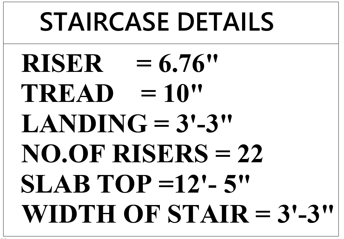
- Stairs Width :- 3'-3"
- Landing Size :- 3'-3"
- Total Number of Risers :- 22
- Tread :- 10"
- Riser Height :- 6.76"
Stair Section Details :-
The staircase section provides insight into vertical dimension and reinforcement detailing are :-
- Total Height (floor to slab top) :- 12'-5"
- Landing Level :- +5'-7½"
- Main Reinforcement :- 10 mm bars @ 6” C/C
- Distribution Steel bar :- 8 mm bars @ 6” C/C
This section also clearly marks :-
- Slab level for building
- Mid-landing level
- Stair reinforcement direction.
This staircase is structurally designed using RCC :-
- Main Steel Bars :- Placed in the direction of flight to main bars (10 mm dia @ 6” C/C)
- Distribution Bars :- Perpendicular to bars (8 mm dia @ 6” C/C)
- Proper staircase support and bar anchorage ensure stability and durability.
Why This Stair Design Works :-
- Space Efficient :- Fits within limited shaft dimensions.
- Safe Design :- Comfortable riser-to-tread ratio.
- Easy Construction :- Reinforcement bars are standard and easy to bend on-site.
- Aesthetic Layout :- Clean plan and section lines for visualization.
Conclusion:-
Understanding stair plan and section detail drawings is essential for both civil engineers and architects. This example provides clear insights into stair planning, structural detailing, and execution. Save this reference for future construction projects or use it for academic learning.


Post a Comment